
Every logistics operation that bills by weight or volume faces the same challenge: packages arrive in thousands of different shapes and sizes, and capturing their exact dimensions accurately, at speed, is operationally expensive when done manually. A warehouse processing 5,000 shipments per day with manual tape measurement requires approximately 5–10 operator-hours per day just for dimensioning — at an error rate of 5–12%. Automated dimensioning technology eliminates both the labor cost and the error.
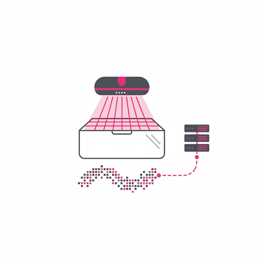
A structured light system projects a pattern — typically a grid or set of parallel lines — onto the surface of the object being measured. One or more cameras capture how this pattern deforms as it wraps around the object's surface. Algorithms reconstruct the 3D geometry from these deformations with sub-millimeter precision.
Structured light is the most widely deployed technology in static parcel dimensioners due to its accuracy and relatively low cost. It performs best in controlled lighting environments and works reliably on standard packaging materials.
ToF sensors emit infrared light pulses and measure the time each pulse takes to return after reflecting off the package surface. Since the speed of light is constant, return time directly translates to distance. By sweeping or using an array of ToF sensors, the system builds a complete depth map of the package in milliseconds.
ToF technology is robust in variable lighting conditions and handles irregular or dark-colored packages well. It is commonly used in in-motion dimensioning gates on high-speed conveyor lines.
A laser line is projected across the package perpendicular to the direction of travel on a conveyor. A camera positioned at a fixed angle captures the shape of the laser line as it passes over the package. By analyzing how the line curves and shifts, the system calculates the package's height profile point by point. Multiple laser lines or a scanning head cover the full length of the package as it moves.
Laser triangulation is one of the oldest and most reliable dimensioning methods. It excels at high-speed in-motion applications and handles packages with complex shapes or overhanging elements.
Two cameras separated by a fixed baseline capture the same scene from slightly different angles. By comparing how points in the two images differ (disparity), the system calculates depth using triangulation — the same principle as human binocular vision. Stereo vision systems can measure packages without projecting any light, making them well suited for applications where ambient light is variable.
The entire cycle typically completes in under 500 milliseconds for static systems and under 100 milliseconds for high-speed in-motion systems.
In-motion systems must synchronize measurement with conveyor speed using encoder-based triggering to compensate for belt velocity, requiring more sophisticated signal processing. Static systems have no motion compensation requirement, allowing higher precision with simpler sensor configurations — the trade-off is that throughput is limited by operator speed.
LiDAR uses pulsed laser light and measures return time or phase shift to build point clouds, similar to ToF sensors. Structured light projects a pattern and analyzes its deformation. LiDAR performs better at longer ranges and in variable lighting; structured light typically achieves higher resolution at short range for package-level measurement.
Transparent or highly reflective surfaces (glass, clear polybags, mirror-finish foil) can interfere with optical sensors. Most commercial dimensioners are calibrated for standard cardboard and matte plastics. Some systems offer supplemental lighting or alternative sensor configurations for difficult surfaces.
Temperature changes cause thermal expansion in sensor hardware and mounting structures. High-performance systems include automatic temperature compensation and specify operating ranges (typically 5–40°C). Calibration should be performed after significant temperature changes in the facility.
A point cloud is a set of data points in 3D space, each representing a measured location on the package surface. The denser the point cloud, the more accurately the system reconstructs geometry and calculates the bounding box. Modern systems generate tens of thousands of points per scan.
_vector.svg)